Silicon Carbide (SiC) technology VS IGBT technology
The following is a professional comparative analysis of Silicon Carbide (SiC) technology and IGBT technology, covering material characteristics, working principles, and differences in practical applications:
I. Comparison of Semiconductor Material Characteristics
| Dimension | Silicon Carbide (SiC) | Silicon-based IGBT |
|---|---|---|
| Bandgap | 3.26 eV (Wide bandgap) | 1.12 eV (Narrow bandgap) |
| Breakdown Electric Field Strength | 3 MV/cm (High) | 0.3 MV/cm (Low) |
| Thermal Conductivity | 4.9 W/cm·K (Fast heat dissipation) | 1.5 W/cm·K (Slow heat dissipation) |
| Saturated Electron Drift Velocity | 2.0×10⁷ cm/s (Excellent high-frequency performance) | 1.0×10⁷ cm/s (Frequency lim |
Core Differences:
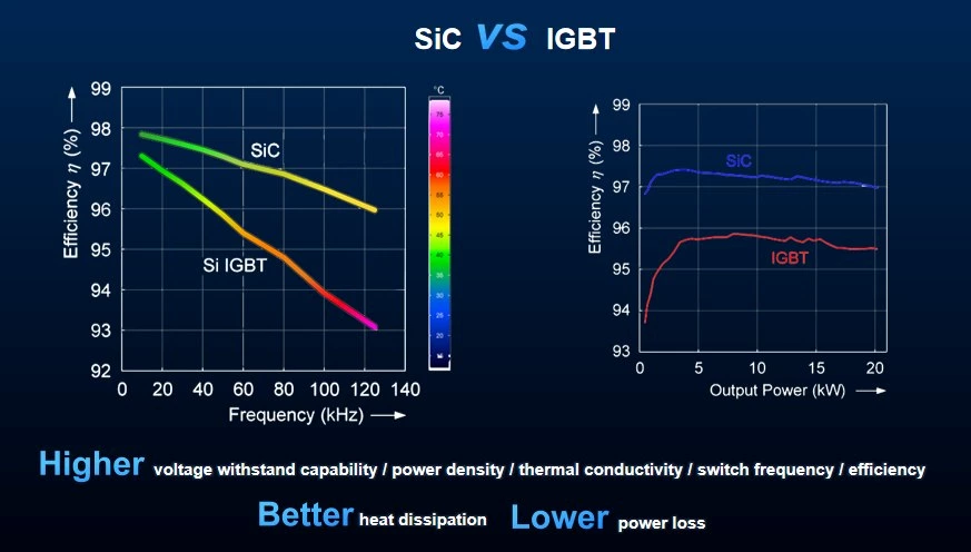
The wide bandgap characteristic of silicon carbide gives it innate advantages of high voltage resistance, high temperature resistance, and low loss, making it suitable for high-frequency and high-power scenarios.
II. Differences in Working Principles
1. IGBT (Insulated Gate Bipolar Transistor)
- Structure: Made of silicon-based material, combining the characteristics of MOSFET and BJT, and its conduction is controlled by the gate voltage.
- Switching Mechanism:
- When conducting: Carriers (electrons and holes) participate in conduction simultaneously, and the on-resistance is low.
- When turning off: There is a "tail current", resulting in relatively high switching losses.
- Limitations:
- The switching frequency is limited (usually < 20kHz), and the losses increase sharply at high frequencies.
- The performance deteriorates significantly at high temperatures (the reliability decreases when the junction temperature > 150°C).
2. Silicon Carbide MOSFET
- Structure: Made of silicon carbide material, a pure unipolar device (only electrons conduct electricity).
- Switching Mechanism:
- When conducting: Electrons pass quickly through the low-resistance channel, and there is no minority carrier storage effect.
- When turning off: There is almost no tail current, and the switching losses are extremely low.
- Advantages:
- Supports high-frequency switching (up to 100kHz+), suitable for high-frequency topologies (such as LLC resonance).
- Strong high-temperature stability (junction temperature tolerance > 200°C), and no complex heat dissipation design is required.
III. Comparison of Key Performance Parameters
| Parameter | SiC MOSFET | Silicon-based IGBT |
|---|---|---|
| On-resistance (RDS(on)) | 10 mΩ (50% lower at the same voltage level) | 20 mΩ |
| Switching Losses | Reduced by 70% (The advantage is more significant at high frequencies) | High (Increases linearly with the increase of frequency) |
| Reverse Recovery Time (trr) | Close to 0 ns (No reverse recovery problem) | 100~500 ns (Generates additional losses) |
| System Efficiency | Improved by 2-3% (Typical value for photovoltaic inverters) | — |
| Volume/Weight | Reduced by 30-40% | — |
IV. Application Scenarios and Cost Analysis
1. Applicable Scenarios
- SiC:
✅ High-frequency and high-power density scenarios (such as photovoltaic inverters, electric vehicle chargers)
✅ High-temperature environments (such as household energy storage systems without forced heat dissipation)
✅ High-end markets sensitive to efficiency/volume (the European Union, North America) - IGBT:
✅ Medium and low-frequency, cost-sensitive scenarios (low-end inverters, industrial frequency converters)
✅ Supported by a mature supply chain (The price is 30-50% lower)
2. Cost Comparison
- SiC Devices: Currently, the price is about 2-3 times that of IGBTs, but the system-level cost (heat dissipation, capacitors, inductors) can be reduced by 20%.
- Trend: With the increase in production capacity (expansion of production by Wolfspeed, Infineon, etc.), the cost of SiC is expected to decrease by 40% in 2025.
V. Industry Certification and Reliability
- SiC Advantage Certifications:
🔵 Efficiency Certification: TÜV Rheinland's actual measurement shows a conversion efficiency of 98.5% (CEC weighted).
🔵 Life Test: The MTBF (Mean Time Between Failures) > 100,000 hours at 85°C/85% humidity.
🔵 EMC Performance: Meets the EN 55032 Class B standard (Lower electromagnetic interference). - Warranty Strategy:
- SiC Inverters: 5-year standard warranty (extendable to 10 years), with a failure rate < 0.2% per year.
- IGBT Inverters: Usually with a 3-5-year warranty, and the failure rate > 1% per year (in high-temperature environments).
VI. Future Trends
- SiC Penetration Rate: In 2023, the proportion of SiC in the field of photovoltaic inverters reached 15%, and it is expected to exceed 50% in 2030 (predicted by Yole).
- Technological Iteration:
- Trench-gate SiC MOSFET (Reducing on-resistance).
- Integrated modules (such as All-in-One power blocks).
Conclusion:
Through the three major advantages of high frequency and efficiency, high temperature and voltage resistance, and system simplification, silicon carbide technology is rapidly replacing IGBTs and becoming the core driving force of new energy power electronics. For customers who pursue long-term benefits and reliability, SiC is an inevitable choice in the next decade!